Understanding Cutting Tool Geometry
March 27, 2018
0
No matter how robust and powerful your on-site machining equipment is, if the tool bit isn’t appropriate your results will suffer. Not only should the tool be sharp and inserted securely, having an appreciation of the cutting tool geometry will help you ensure it is right for the job.
If you’re an experienced machinist, then no doubt you’ll have this covered. But for those new of you to the profession, this YouTube video created by Learn Engineering gives a clear explanation of how the geometry of a single point cutting tool works when removing material.
Key cutting tool geometry takeaway points from the video are:
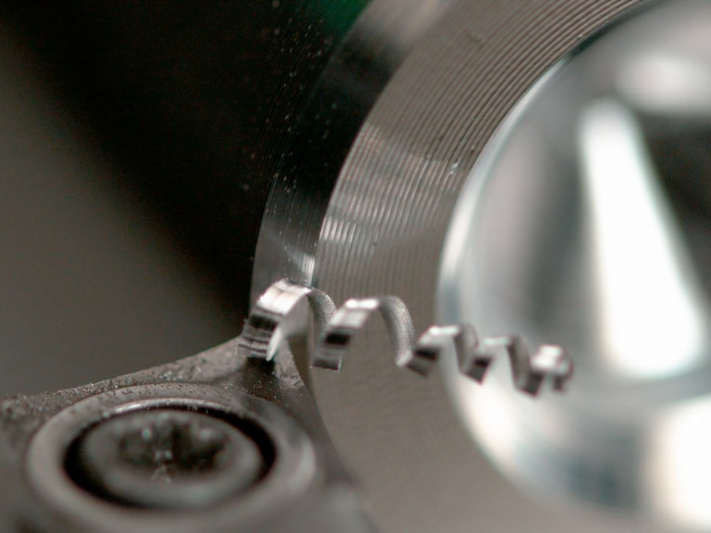
- To remove a metal chip from a work piece you have to cut along at least 2 surfaces; a main cutting edge and an auxiliary cutting edge.
- The main cutting edge cuts the main portion of the chip while the auxiliary cuts the second surface and removes the material.
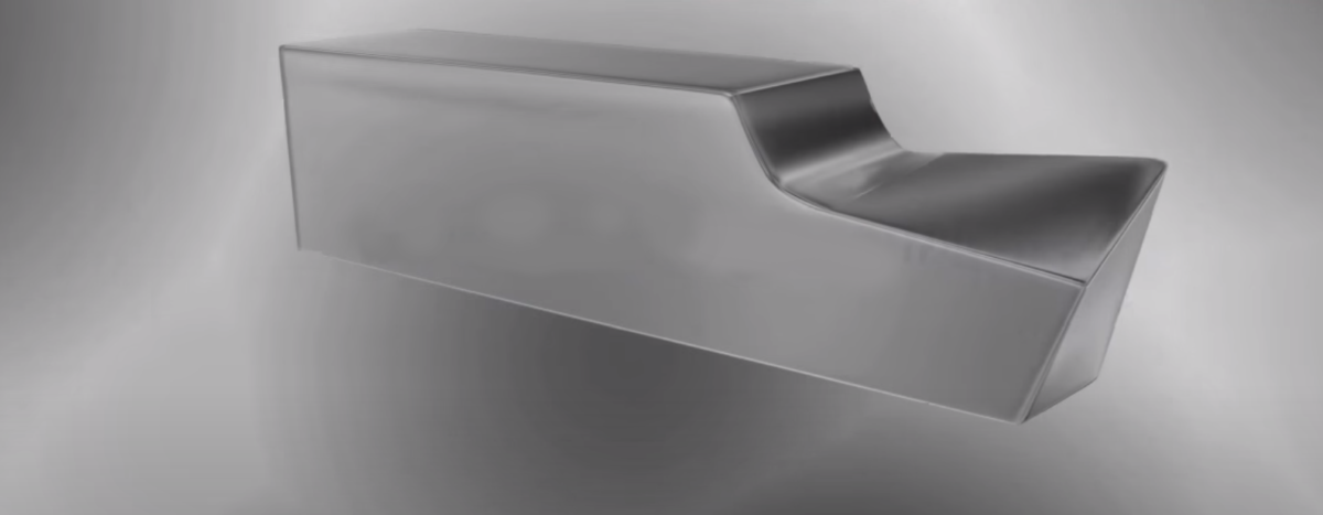
- The corner on the tool (shown in the video) is known as the ‘nose’.
- Nose radius effects the surface finish and the strength of the tool.
- Material removal by the main cutting edge is easier when the material’s flowing surface is at an angle. This angle is known as the rake angle of the tool, or the back rake angle.
- The back rake angle affects the chip thickness and the force of the cutting.
- To avoid the rubbing of the cutting tool on the workpiece the relief angle avoids rubbing of the tool on the workpiece.
- Similar relief and rake angles are also given to the auxiliary cutting edge.
In summary, there are 7 parameters that define the geometry of a cutting tool
- Back rake angle
- Side rake angle
- End relief angle
- Side relief angle
- End cutting edge angle
- Side cutting edge angle
- Nose radius
If you have a potential project needing portable machine tools please click here to get in touch.

Decommissioning Case Study Pack
Learn how portable machine tools solved four tough decommissioning challenges