How to Ensure Flange Integrity in LNG Plants

February 12, 2015
0
The process of converting natural gas into liquid form enables more efficient transport and storage but is widely held as hazardous and expensive, especially with the need for expensive cryogenic tanks used to store the liquid at extremely low temperatures. Due to the flammable nature of the gas involved, the commissioning of an LNG plant demands that stringent safety measures and precautions are adhered to.
This article aims to provide an overview of some key considerations for minimising the failure of pipe flange joints.
The importance of flange integrity
With the stakes being so high, ensuring the integrity of all LNG pipe flange joints is absolutely critical. The high risk nature of the process and the need for multiple layers of pipe insulation materials makes pipe maintenance very difficult once the plant is operational. This means a ‘right first time approach’ with zero defects at the point of commissioning should be the primary goal.
Best practice when designing an LNG plant suggests keeping the number of flange joints to a minimum, but inevitably there will be many areas (such as valve connections) where there is no other alternative.
Provided best practice and a relevant standards are adhered to the risk of leakage from flange joints can be kept fully under control.
Let’s first look at the different types of systems used in an LNG plant.
These fall into four categories each with varying characteristics;
- Main process systems – (low and high pressure LNG systems on the plant and the loading/unloading systems between the ship and the storage tanks.
- Auxiliary process systems – hydrocarbon drain systems, plant fuel, cooling systems.
- Utility systems – vary greatly according to the type of plant.
- Fire protection systems – spraying system , water curtains, foam generation
In each of the four above categories there are many steps which can be taken to reduce risk of leakage.
Check flanges for damage before installation
Even a small amount of damage to a flange face can cause a joint to fail. Typical types of damage include:
- Scratches – often caused by items such as a wire brush or chisel, sometimes seen in transit and from the removal of protective coatings.
- Gouges– created by a dull object dragging across the flange face, such as a screwdriver, flange Often caused in transit from the fabrication plant to site, or during commissioning.
- Pits – small rounded areas of material loss, sometimes in groups and caused by corrosion. However, these after normally created after the plant has been operational for some time.
- Dents – caused during the installation and commissioning phases through impact with equipment such as cables, rigging and positioning of mating flanges.
Pay particular attention to scratches running across the ridges as these create a path for potential leaks. (Refer to ASME PCC-1 guidelines).
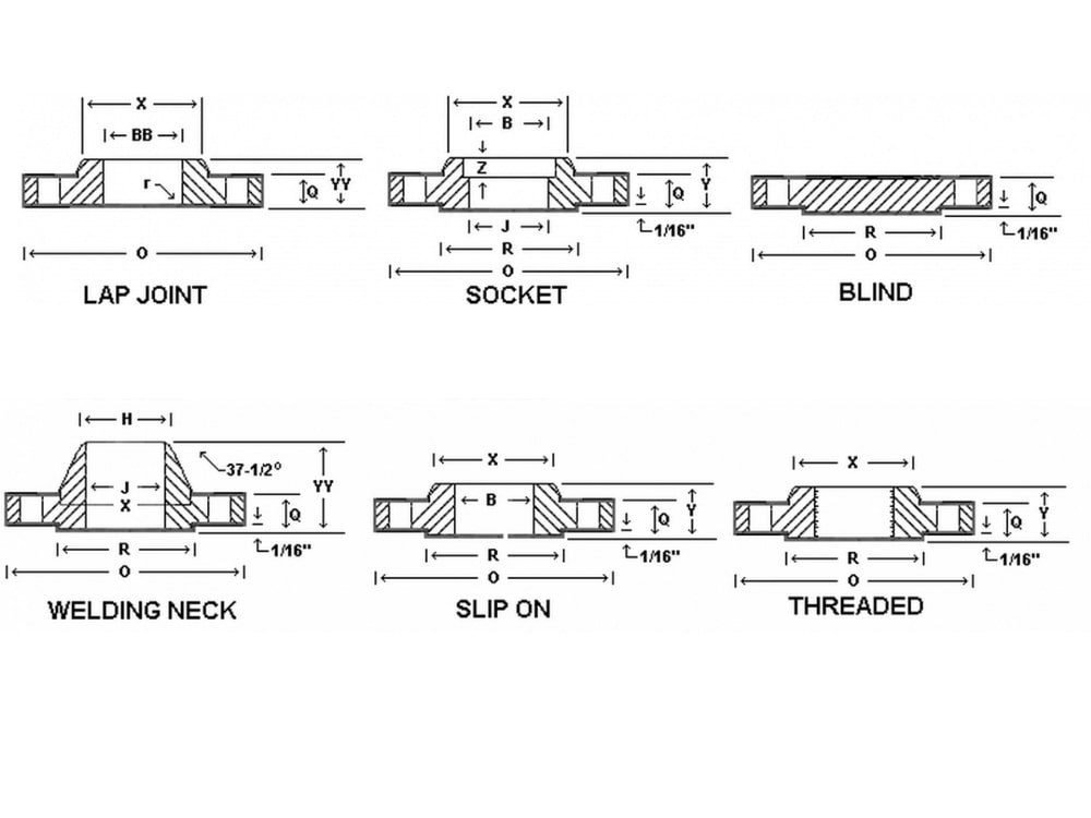
Ensure you use the correct flange surface finish
A portable flange facing machine can be used either at the prefabrication location or on-site to ensure the required finish is achieved. Referring to the ASME b16.5 standard for flange finishes is recommended, plus ASME 16.20 and 16.21 standards for gasket surface finishes.
Use the correct gasket type
Gaskets used in the main process systems will need to be capable of maintaining a seal at temperatures as low as -162 degrees centigrade. These are often made from compound materials, such as ’semi-metal’ gaskets which include a hoop containing expanded graphite or PTFE filler.
You should never use gaskets not rated for the pressure to be applied, even if the gasket is temporary for testing purposes. ASME Standards and Certification (PCC-1-2010) advise that temporary gaskets should be used with caution only and that gaskets are not reused.
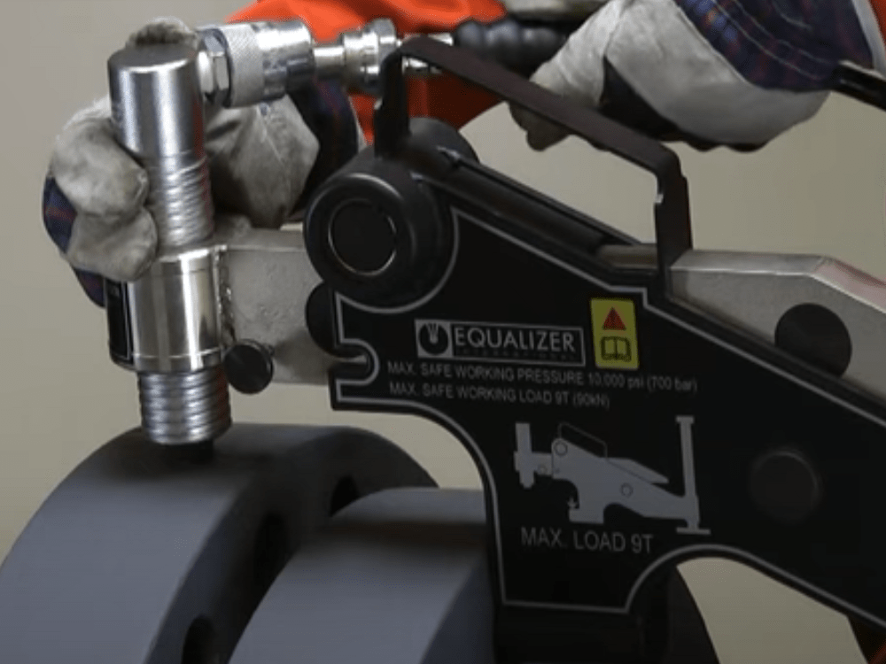
Correct bolt tightening
As you would expect, bolt tightening has a huge impact on the integrity of the flange joint and is a highly specialised area. In 2008, Pumps & Systems magazine published an article which was created following the review of 100 failed gaskets. 68 of these failures were attributed to under compression and 14 due to over compression). It is therefore vital to adhere to relevant industry standards, such as ASME PCC-1 ‘Guidelines for Pressure Boundary Bolted Flange Joint Assembly’ (BFJA). This not only covers the equipment and process specification, but also defines the requirements for the training and qualification of bolted joint assembly personnel.
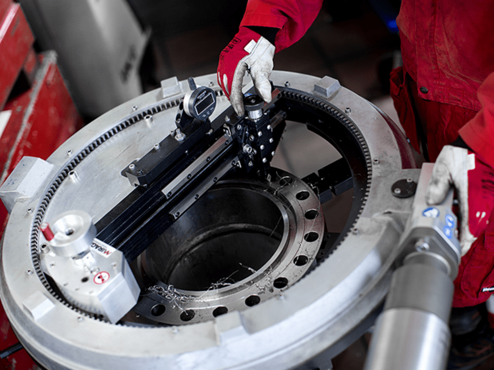
Ongoing maintenance
Having a strong focus on ‘zero defects the point of commission’ should minimize the need for flange joints to be dismantled for maintenance. However, should this be absolutely necessary, there is a wide range of Mirage flange facing machines and pipe cutting tools available, which can be used easily on-site.